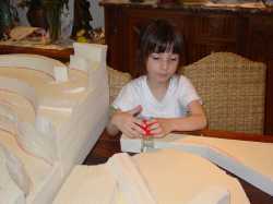
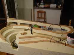
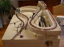
This is a kind of one minute project, spaghetti plate in HOe.
The goal is simple: obtaining something that works within a small timeframe and with an as low as reasonable budget.
Let say, all inclusive, less than 130 Euros/80 Pounds/160 USD. (Approximated conversions!)
Other furniture:
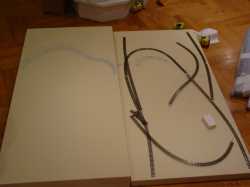
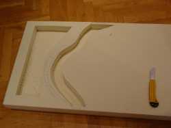
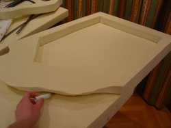
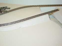
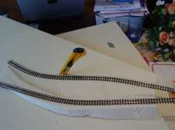
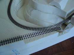
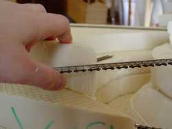
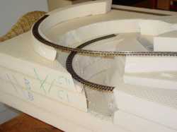
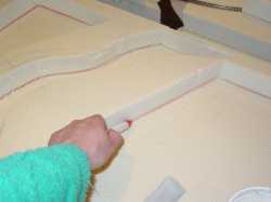
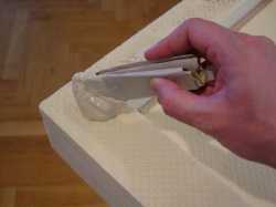
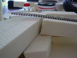
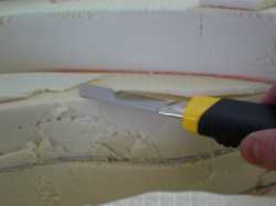
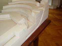
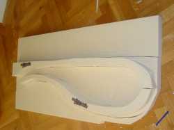
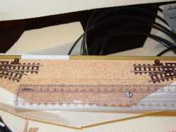
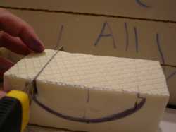
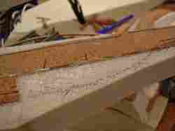
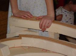
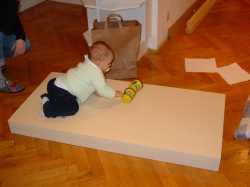
This kind of high density Styrofoam 50 mm thick plates is strong enough for model trains business. Furthermore, the plates are glued together, enhancing the robustness of the structure. 40 mm plates or even thinner are available. They are also easier to cut. However, you then need more time to achieve a given 3D geometry. Furthermore, the drawing has been done on a 5mm squared paper -- an extremely common one -- and the ratio is then 1/10 against the paper which makes it easy to work out.
| |||
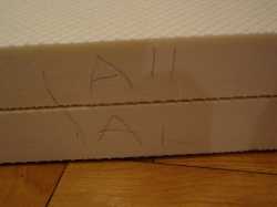
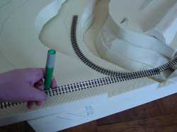
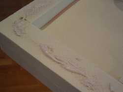
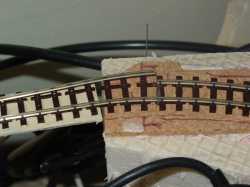
These simple marks are soon a must... although one has to remember about them before cutting anything! I made one small mistake that had only an impact on the mark,
leading me to be more cautious later on. These marks are just needed regularly all along the design and the construction!
|
Minip_Im_002.jpg 401.94 KB |
Minip_Im_003.jpg 353.84 KB |
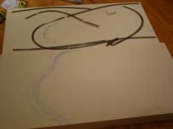
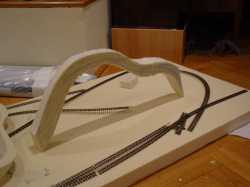
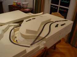
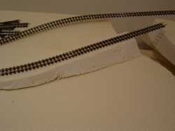
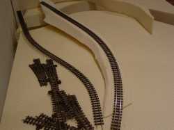
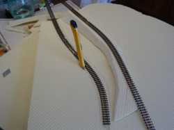
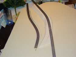
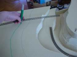
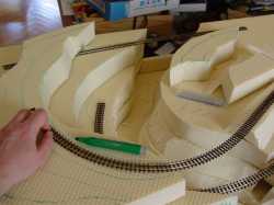
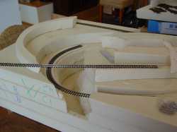
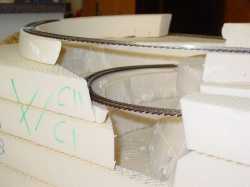
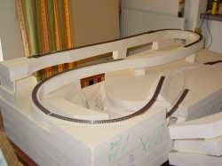
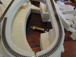
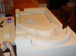
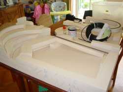
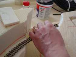
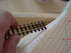
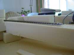
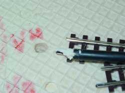
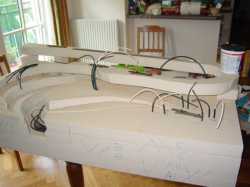
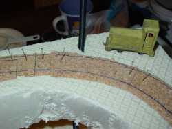
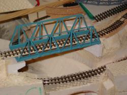
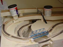
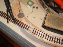
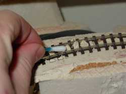
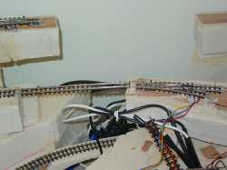
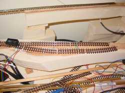
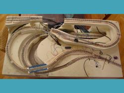
A first rough trial enables a check of feasibility of a track layout. At this stage, we are still far from a final version. Basically we just reproduce the paper drawings. Pins maintain the flexible Roco tracks.
Pins are very useful since they do not leave any trace on the Styrofoam and, at the same time, do not need to be inserted vertically, thus being more efficient in maintaining the track on the plate.
Flexible tracks tend to produce quite a bit of a constraint to get back to their original shape. All of this allows the test of the curves with a freight car and leads to some corrections.
|
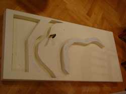
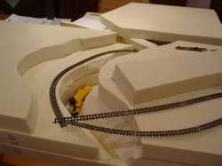
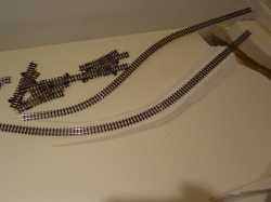
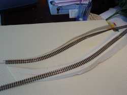
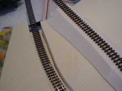
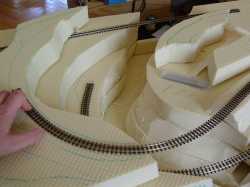
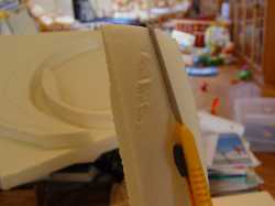
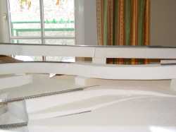
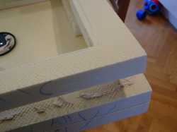
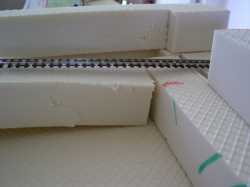
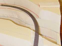
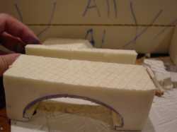
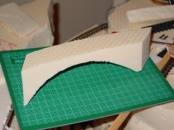
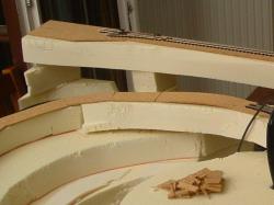
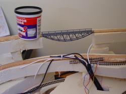
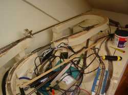
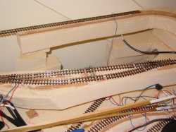
The gorge and the river, that are justifying this layout by themselves, are drawn on the Styrofoam plate number 2. The shape of it does not need to be complex, first because mother nature would choose
the simplest path, then because we need to cut it with our cutter! Just remember that the final goal is to see the trains as long as possible. The orientation of the river is defined by this last criteria.
|
Minip_Im_004.jpg 405.16 KB |
Minip_Im_005.jpg 405.99 KB |
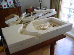
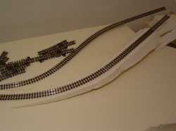
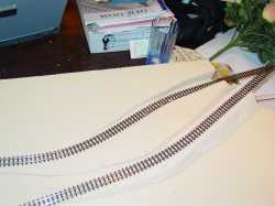
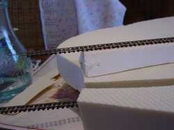
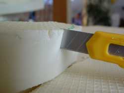
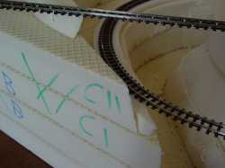
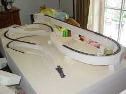
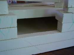
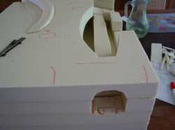
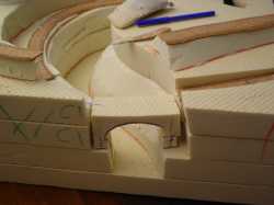
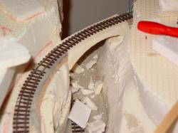
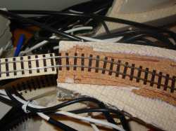
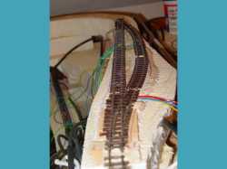
The first plate is kept as it is. For the other one, we seek a gain on overall mass. Therefore any chance to remove some Styrofoam is taken without putting the structure at risk. A small amount of Styrofoam is kept at each river
ends. This is to allow easy hand carrying of the plate as well as to prepare for the setup of the river. The amount of material left at each end proved to be too little mechanically and the Styrofoam got cut. This had no impact
on the work. Otherwise, since the Styrofoam is not too expansive another plate would have been used and this one cut later on into pieces to generate the mountains. The river is too narrow and an additional cut is performed.
|
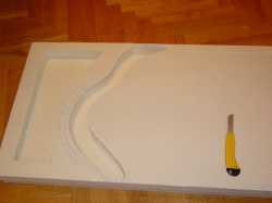
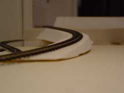
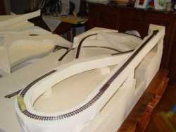
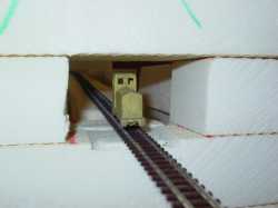
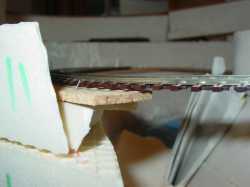
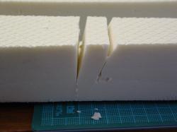
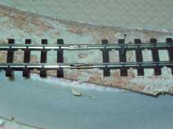
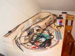
The river is deep down below the main level and not too narrow. One could have made it really narrow as a steep gorge but the tracks would not have show up... which would have been no fun anymore!
|
Minip_Im_006.jpg 415.04 KB |
Minip_Im_007.jpg 431.87 KB |
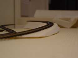
With another exposure this is still ok. One should never forget that the potential observer may look from different angles and under variable luminosity.
|
The left over from the river gives me some ideas on how to build light mountains or hills in the future!
|
Minip_Im_008.jpg 402.30 KB |
Minip_Im_009.jpg 480.08 KB |
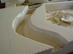
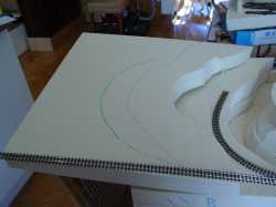
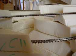
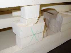
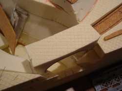
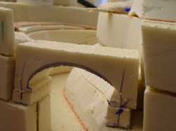
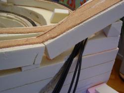
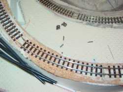
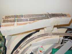
The next steps are based on the same principles. The third plate is even easier to make as the structure constraints are not applicable anymore. It can be cut into two pieces addressed separately.
Slopes are obtained using the cutter and can still be modified wouldn't they fit properly. Once again, the inner part of the plate is removed. From this stage on, it becomes clear that too much was removed
from the second plate. The gap will have to be filled partially later on for the lower track going into the mountain.
|
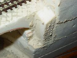
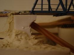
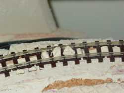
Close up on the river: it does not show any major discrepancy. We really have a gorge that does not take too much space on the layout!
|
Minip_Im_010.jpg 478.38 KB |
Minip_Im_011.jpg 363.21 KB |
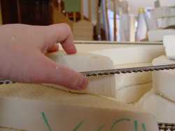
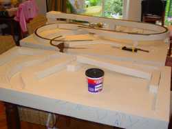
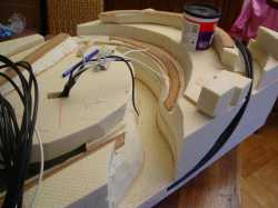
Plate are not sided. This makes it easy to copy the shape of the river before cutting the Styrofoam. One has just to remember to add or remove some of the Styrofoam to take the hill shapes into account. This can be done "on site".
|
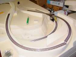
After the fourth plate is positioned, it is high time to verify the position of the tracks which will be at this level... simply to check the foreseen schemes!
|
Minip_Im_012.jpg 411.04 KB |
Minip_Im_013.jpg 414.34 KB |
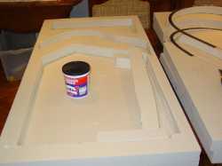
and try some optical tests! Nothing is better than seeing some intermediate results in real life!
|
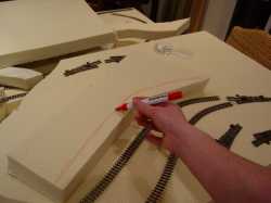
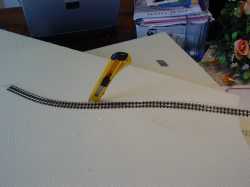
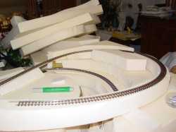
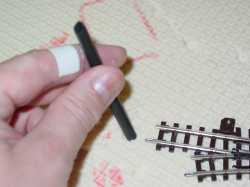
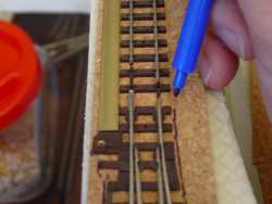
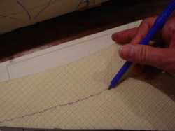
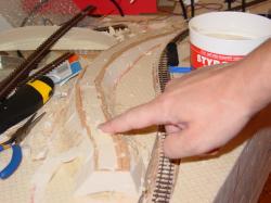
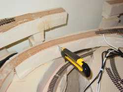
As expected a ramp is required. The idea is to make it from some Styrofoam left over from previous stages. This strategy may not prove to be the most efficient, particularly in view of the other strategy tested for the second track. Note the use of my hand: one finger guides the rest of the hand... and the pen! It shows where to cut. This tool is very sophisticated: the angle of the hand also makes the distance according to the user requirements! The second line is drawn based on the first one according to the size of the track. |
Minip_Im_014.jpg 397.72 KB |
Minip_Im_015.jpg 326.83 KB |
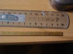
This is the result based on a 50 mm plate, using about 500 mm track, which correspond to 43.5 m and a 10% ramp.
|
The same ramp, the picture is taken without flash. This seems to be OK. Let's change again the observation angle.
|
Minip_Im_016.jpg 412.24 KB |

Minip_Im_017.jpg 443.64 KB |
Ouch! unfortunately the ramp it too steep! If not against the real situation regarding the narrow gauge railways, the ramp will not be nice to see. One of the reasons is that, on a model train layout,
the distances are not properly scaled -- except for Proto people... who really need large rooms -- and some compromises have to be made to restore some credibility for an external observer.
|
Let's check again! Is it so bad?
How to change the ramp? Is it really needed?
Is the overall track positioning OK, not taking into account the ramp?
One need to answer to all of these questions.
|
Minip_Im_018.jpg 437.16 KB |
Minip_Im_019.jpg 405.18 KB |
Check up: from the rear side.
|
Check up: from an axial point of view.
The solution will be to get the other track down so the ramp can be reduced.
|
Minip_Im_020.jpg 435.07 KB |
Minip_Im_021.jpg 322.89 KB |
From the ground level, the ramp is obviously too steep
|
As you may have noticed, on the previous pictures, the ramp had already been addressed!
An additional piece of Styrofoam was just added there to show how it was looking like.
Now let's see the reduced ramp. No question, it looks much better!
By the way, the track layout is rather convincing.
|
Minip_Im_022.jpg 320.49 KB |
Minip_Im_023.jpg 405.83 KB |
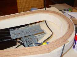
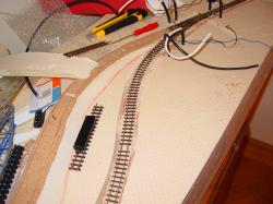
Enough for the upper track, let's address the lower one... from the station and switch point of view! The approach is totally different... and by far more efficient. (It took a long time -- more than two hours altogether -- to create and adjust the previous ramp). The Styrofoam present some flexibility which can be used to our benefit. |
The track is positioned and pined. The cutter just needs to follow the given shape. The plate gets easily cut provided the blade be maintained firmly and the movement made smoothly, starting again if needed.
Please not that along this whole cutting process, because I tried to save some money on the cutter, I used many blades and exploded three cutter safety locks...
At the end, I bought a medium quality cutter... that you will discover after the picture numbered 51! |
Minip_Im_024.jpg 437.72 KB |
Minip_Im_025.jpg 337.99 KB |
The cut is done approximately, according to what my eyes tell me. This is not a scaled copy of any real track! We just have to care about some realistic aspect of the whole layout. |
This is the first trial to generate a ramp that way. Part of the plate underneath has been removed to allow the ramp to be tuned.
|
Minip_Im_026.jpg 424.61 KB |
Minip_Im_027.jpg 405.08 KB |
Same with the flash, one does not see any major mistake.
|
The front view confirms this first feeling. Ramps are realistic and the switch looks correct. We may expect some nice pictures when the trains will be on the tracks.
|
Minip_Im_028.jpg 436.31 KB |
Minip_Im_029.jpg 337.53 KB |
The size of the module forces some technical choices that are not the most convenient! It will be necessary to build a structured wall to maintain the upper track over the lower one.
This will be a good reason to dig into the scenery aspects of the module!
|
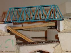
A closer look is mandatory. The height between the two tracks has to fit the main condition: a train getting on the lower track must be able to cross under the bridge sustaining the upper track.
There's not much that could be given away! Fortunately the narrow gauge railways can survive without the heavy construction needed for standard railway. Anyway, the company did not have enough money to be in better shape!
|
Minip_Im_030.jpg 329.57 KB |
Minip_Im_031.jpg 362.79 KB |
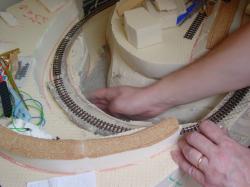
The track on the third plate comes along the fourth plate. The main advantage of model railroad, when not copying exactly with the reality, is that one can adjust the shape of the hill to address the technical requirements! The strategy with our best available tool, the hand, is still valid... provided some tiny adaptations are made. |
An upper view tells us more about the tracks. The descending track is in front for two main reasons:
|
Minip_Im_032.jpg 399.11 KB |
Minip_Im_033.jpg 415.18 KB |
The Styrofoam is cut as already said. The guiding finger is replaced by a piece of track and the eyes.
|
If the end of he piece of track is over the track on the third plate, then the marker, previously set to a correct position will just follow the required shape. The only requirements are a fourth plate properly positioned for its front and rear borders and a guiding piece of track maintained parallel to these borders. There's no such a requirement as to have a extreme precision for this business. |
Minip_Im_034.jpg 429.94 KB |
Minip_Im_035.jpg 410.46 KB |
One can see the result of the previous step while we now address the fifth plate. The eye is our main judge to check the position of the track.
|
Once again, the marker is enough. The 50 mm difference between the fourth and the fifth plate is adequate in regard to the chosen ramp.
|
Minip_Im_036.jpg 425.20 KB |
Minip_Im_037.jpg 286.64 KB |
The Styrofoam piece sees its end adjusted to the river border in one cut.
|
The ramp after the upper bridge needs to be changed as it clearly appears on this picture. The gorge will be reshaped later on. It looks too straight!
|
Minip_Im_038.jpg 302.83 KB |
Minip_Im_039.jpg 285.53 KB |
The cut has to be chosen very carefully and several eye checks are necessary.
|
The cut point is now chosen and the track is pressed against the Styrofoam to leave a mark on it. This last is enough for our goal.
|
Minip_Im_040.jpg 288.80 KB |
Minip_Im_041.jpg 284.14 KB |
Cutters are very nice tools to us. Their blade can accept some torsion, or like here, being a guide.
The angle is eye chosen from the beginning and pulling regularly on the cutter gives the exact required ramp until the other end of it.
|
The ramp is positioned to check its space requirements as well as its slope. Both are OK, the slope is constant.
|
Minip_Im_042.jpg 354.70 KB |
Minip_Im_043.jpg 358.40 KB |
All the positioning marks are so far addressing the needs.
|
The track is pinned in place to check if the slopes are not showing sudden gradients that would be enough to justify some corrections or even a full change of the plate arrangements.
Nothing frankly wrong is to be observed there. The upper-lower bridge crossing is even realistic.
|
Minip_Im_044.jpg 329.75 KB |
Minip_Im_045.jpg 304.88 KB |
From the ground level the slopes are constants. The overall impression is rather good.
|
This difficult step being over, we can address the next part of the main ramp to let the tourist train climbing to its final destination, the upper station in the mountain while the mine train would take the lower
track into... Into... oups! Into nothing so far! I totally forgot the follow up of this track! This will make my life slightly trickier later on! I know this fact but this is too late for the time being and the whole upper r
amp has to be finished in order to get a general overview of the layout. The lower track enters the mountains and stays flat there.
|
Minip_Im_046.jpg 419.46 KB |
Minip_Im_047.jpg 352.03 KB |
The upper ramp has a very constant slope. The upper line bridges are so far simulated by Styrofoam strips.
|
Except for the highest curve for which space is short and the adjustment has to be well tuned, there's no problem getting to the top of the hill. The station at the bottom has to be slightly relocated in order to win the few centimeters that were missing for the upper track to fit properly. Tests with coaches or the small engine confirm the radius not to be too small. Thanks to the HOe which allows many possibilities on small layouts and also thanks to the pins which allow easy repositioning of the tracks! The upper station has a switch to store a small train or an engine. |
Minip_Im_048.jpg 403.25 KB |
Minip_Im_049.jpg 363.65 KB |
Spaghetti gets here all its meaning! (Thanks to
Ptitrain
and to our Swiss friends for this very pictorial expression!).
|
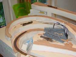
Another general overview confirms the overall good looking of the layout in such a small surface, except for the lower station with will have to be very small. Note that at this stage, several extension options are left for a possible future:
|
Minip_Im_050.jpg 407.10 KB |
Minip_Im_051.jpg 396.61 KB |
This point of view enables us to see the various levels of the tracks. Our friend Charles from Bordeaux will surely recognize the small
home made narrow gauge railway engine
which is used here for checking purposes!
|
Before even starting with the glue, I rather address the lower track after being close to the river. This one has to enter the mountain and should allow connection to future parts of the layout if needed. Whatever is coming next, I would better make a hatch to put back on track the derailed trains. My new cutter is really good at the job! |
Minip_Im_052.jpg 332.85 KB |
Minip_Im_053.jpg 329.08 KB |
Now that plate number 3 and 4 are cut, the last ramp support needs to be stabilized. This will be addressed later on. One can see how making a bridge's shape under the temporary bridge (behind) improves the general aspect! |
The upper plates have been moved thanks to my wife's help. The second plate is already on the first one. The glue is showing up! |
Minip_Im_054.jpg 381.20 KB |
Minip_Im_055.jpg 349.17 KB |
Taking advantage of the situation, we can check for the feasibility of a ramp. At first sight the answer is yes. The plate will have to be cut to keep a regular ramp for the lower track. The ramp avoids the fourth plate to be cut, enabling a more robust general structure which will also simplifies the shaping of the hills later on. |
I draw the various borders to make it easy to put the glue only where necessary. Glue should not be put where Styrofoam will be removed afterwards. |
Minip_Im_056.jpg 336.74 KB |
Minip_Im_057.jpg 360.53 KB |
It's so easy... one has just to glue the plates! I do this very fast, forgetting at the same time to take pictures... Grrr! |
Once again, I take advantage of the glue stabilizing a little bit, to cut the plate over the ramp. Accessing the train there must be easy! Do not ask me why, but should a train derail, it would do it precisely there where access is limited and so often as the access is difficult! |
Minip_Im_058.jpg 367.41 KB |
Minip_Im_059.jpg 335.66 KB |
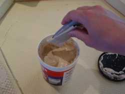
MIMO ! An empty corn flakes box has been stolen from the paper bin and destroyed! Call the police! The guy was also seen wrapping a rectangular piece of it with scotch tape, squeezing it afterwards until it would be more or less flat... It's a good throw away tool to put the glue... so good that I still did not throw it away! |
This glue should not be flat toasted (the flexible one could, but it is very inconvenient to use). One does not need to fully cover the surface to be glued but should address each area. This way, the structure is resistant. Constraints on it are not many, except when carrying the layout. |
Minip_Im_060.jpg 341.25 KB |
Minip_Im_061.jpg 314.60 KB |
The glue has been set up. Not too much, not too little. |
I would not council putting glue nearby the external borders and borders in general. The glue migrates out when the two parts are pressed together generating additional work to smooth the borders. |
Minip_Im_062.jpg 347.08 KB |
Minip_Im_063.jpg 337.65 KB |
The work goes on without problems. Note that it is useful to trace the border of small Styrofoam items and to write an ID (can be a sequential number such as 1, 2, 3,...) on both plates receiving the item and on the item itself. |
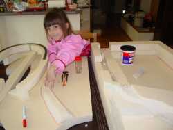
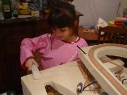
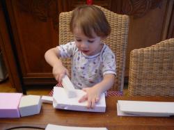
Numerous pins have been colleted during this phase. I just pined them in a piece of Styrofoam so my helping handsome guy from the first picture would not imagine some crazy game to play with! My daughter Camille, who just finished a drawing, helped me to put the pins in a spice bottle. She really wants the train to go! |
Minip_Im_064.jpg 379.88 KB |
Minip_Im_065.jpg 347.83 KB |
Eventually the lower track goes into the mountain thanks to a ramp. |
Do not imagine though that world would be so perfect that everything would fit at once! The upper part of the ramp will need some cutter work... |
Minip_Im_066.jpg 313.40 KB |
Minip_Im_067.jpg 302.68 KB |
and so will also need the lower part! |
The lower track ramp along the river will also have to be adjusted. This is slightly more difficult since the plates in this area are already glued. It is much easier to work the plates in any required position! |
Minip_Im_068.jpg 287.08 KB |
Minip_Im_069.jpg 318.36 KB |
The track is temporarily positioned... |
The previously described method is applied again. It gave good results. Here again a mark on the Styrofoam is generated. |
Minip_Im_070.jpg 292.48 KB |
Minip_Im_071.jpg 286.85 KB |
Now it looks much better. |
But still the technical part has not been addressed. The ramp needs to be adjusted. A small squared piece of Styrofoam is shifted under the ramp to adjust it. As soon as the interval between the track and the Styrofoam disappear, this is done. |
Minip_Im_072.jpg 273.18 KB |
Minip_Im_073.jpg 297.53 KB |
It is high time to check if the ramp answers the needs that justified it. The main reason was to keep the upper plate entire so the structure would not be weakened. The narrow gauge engine fits there. |
Back to work with the glue. My daughter who already helped me with the inner ramp is pressing the first ramp for the upper track. |
Minip_Im_074.jpg 326.56 KB |
Minip_Im_075.jpg 329.84 KB |
I just remembered that I was born with hands! When a train derail, one has to use them... explaining the reworking of the potential connecting tunnel! |
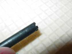
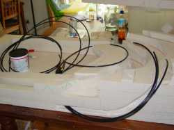
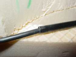
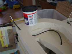
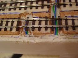
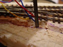
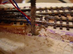
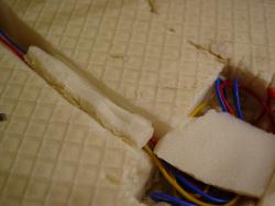
Electricity (Houses lighting, Tracks voltage, and switches commands) needs to be addressed at this stage. The method applied on another project (Austrian village) is used again. Flexible pipes bring the cables from a common starting point to the various locations. It simplifies the process at the time of the construction as well as in case of repairs. Now, to get the pipe through, one has to bore the Styrofoam at the right diameter. A piece of pipe is enough for this provided one makes some teeth at its end. |
Minip_Im_076.jpg 204.93 KB |
Minip_Im_077.jpg 309.69 KB |
Teeth which allow us to use the pipe as a crude oil field bore hole driller! |
The result is exactly what we were looking for. The pipe cuts the Styrofoam which gets inside the void of the pipe. The Styrofoam has just to be extracted from it about every two centimeters. |
Minip_Im_078.jpg 360.49 KB |
Minip_Im_079.jpg 310.13 KB |
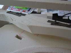
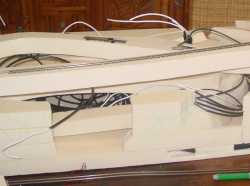
The mountain has been forgotten... or more precisely the need for its cabling. Rather than gluing another plate underneath the whole layout, I create a path for the cables within the first plate:
|
This gives an idea of the cable set to take into account. It is not a complex one but one will still have to mark each pipe and cables! |
Minip_Im_080.jpg 351.94 KB |
Minip_Im_081.jpg 391.56 KB |
The cables are bought, let's check a few issues. My daughter Camille helps me. Surprise! The Scart cables are partially crossed. (I still did not get why by the way!). Fortunately the female-female connector is also crossed!
|
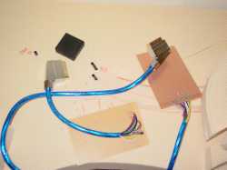
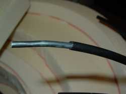
The cable is cut and prepared for soldering. The short part comes from the command box while the longer one is linked to the layout. The longer one will go down to the ground, removing most of the pulling risks. (the styrofoam is not resistant enough to resist important forces applied to it). An extension cable can be added if necessary. |
Minip_Im_082.jpg 381.11 KB |
Minip_Im_083.jpg 346.07 KB |
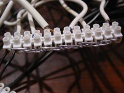
Wires are now soldered to the connection plates. |
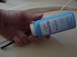
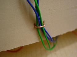
The cable is simply injected into the pipe. Baby powder helps for this business. (The same strategy is used for industrial applications... but with some special creams/fluids). The diameter of the electrical cable is almost equal to the pipe one. This said, if any deformation occurs on the cable -- mainly due to its handling conditions -- it is almost impossible to get it out of more than one and a half meter pipe. The pipes leading to the mountain are two meters long. Therefore, one should start with those longer pipes. If something goes wrong, just pull the cable and use it on smaller pipes. This avoids waste. I have been too optimistic and the 20 meters of cable are not enough, but for the current installed cables (Image 80) |
Minip_Im_084.jpg 331.40 KB |
Minip_Im_085.jpg 254.19 KB |
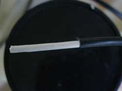
The four wires cable just reappears on the opposite side of the pipe, exactly as expected. |
The baby powder is very useful. Put some in your left palm. Put some from your palm in the pipe. Take the pipe in your right hand and insert slowly the cable with your left hand. First quite fast but soon very slowly. Take care not to wrap the cable. Any small shape change affects the pushing of the cable in the pipe. |
Minip_Im_086.jpg 336.46 KB |
Minip_Im_087.jpg 280.52 KB |
This time, a power cable is inserted (2x0.8 mm2). More rigid, it requires more work. The cable comes out with a little bit of baby powder. This is of course no problem at all. |
Thanks again to my dear one! She noticed that I did not take pictures! As I need to address the crossing, I take advantage of it to redo the upper ramp, based on the parts I made previously using an almost unused plate. This way the ramp slope will be constant. |
Minip_Im_088.jpg 324.17 KB |
Minip_Im_089.jpg 342.84 KB |
I put the power cable for the upper part of the ramp. The glue jar maintains the ramp in place as it is not glued yet! |
Several cables are needed for this crossing, this is why I use the cutter to create a hatch there. |
Minip_Im_090.jpg 353.87 KB |
Minip_Im_091.jpg 347.70 KB |
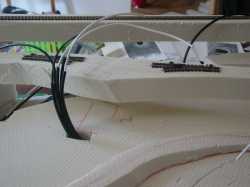
The cables are easily getting through, even space is spared for any additional needs. |
All upper cables are here, only the lower track has to be addressed now. |
Minip_Im_092.jpg 340.90 KB |
Minip_Im_093.jpg 329.06 KB |
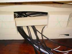
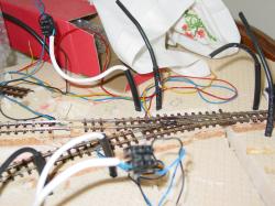
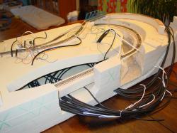
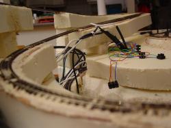
From another angle, once can see the cable jungle underneath! |
The cables are pulled out for the first time. To my surprise they do not need a very large section. I should be able to connect them in situ as previously wished. |
Minip_Im_094.jpg 342.77 KB |
Minip_Im_095.jpg 346.27 KB |
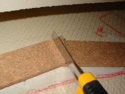
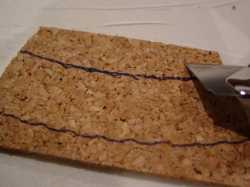
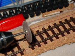
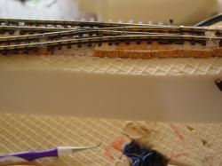
The ballast is cut into a layer of cork. It should reduce the phonic transmission, particularly the effect of the open volume underneath the upper plate. The cut is done in situ. Two pieces are put together so after being cut, they will perfectly fit together. |
The result before the final cut along the track and before bridges are addressed. |
Minip_Im_096.jpg 341.27 KB |
Minip_Im_097.jpg 311.10 KB |
The track is again setup temporarily. The guidance lines to cut the cork are easily made. |
The cutter s maintained strongly at approximately 45 degree angle. The cut is made about two millimeters away from the line drawn previously. |
Minip_Im_098.jpg 346.44 KB |
Minip_Im_099.jpg 308.41 KB |
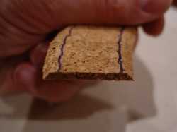
The band comes from a isolation cork layer. One sheet of such cork is enough for the whole module and cost less than sixty pence or a dollar! |
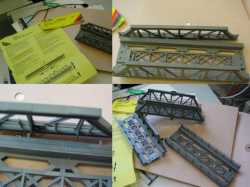
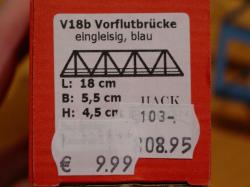
Before constructing home made bridges (which would look better) some bridges from the firm Noch are bought. The just need to be clipped without glue. 10 seconds per bridge are enough! |
Minip_Im_100.jpg 56.17 KB |
Minip_Im_101.jpg 363.91 KB |
Ah! Ah! Ah! Good joke! I just forgot how long would be the smallest train available on the market! The smallest Roco steam engine with a nice Coach would reach 62+96=158 mm I have to move down my switch! |
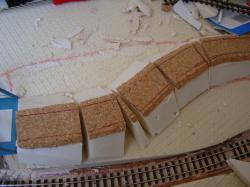
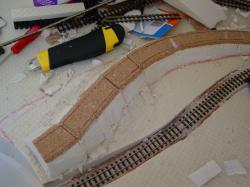
The pieces of cork band are pin maintained. They will be glued later on. |
Minip_Im_102.jpg 363.48 KB |
Minip_Im_103.jpg 354.72 KB |
The low radius upper track curve is almost finished. |
The crossing section on the upper track is also made larger in order to cope with the trains length! A minimum requirement, no? |
Minip_Im_104.jpg 353.71 KB |
Minip_Im_105.jpg 295.12 KB |
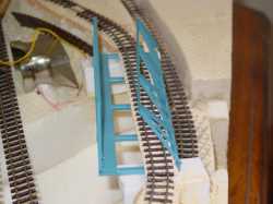
The cork band is adjusted to the lower track radius and ramp. Unfortunately, it does not allow one of the bridges recently bought to fit in! |
The two tracks are now prepared. The bridges on the picture show that a much smaller structure is needed for the lower track. |
Minip_Im_106.jpg 360.73 KB |
Minip_Im_107.jpg 304.30 KB |
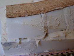
Once again, a temporary solution is retained: making a bridge in a left over piece of styrofoam! A finger guided pen makes the work! |
The drawing is slightly tuned and the cutter starts working! The inner non directly accessible part is left to be cut after the main one. |
Minip_Im_108.jpg 315.40 KB |
Minip_Im_109.jpg 320.25 KB |
The bridge is too large. The cutter makes it come to the right size! |
Which now fits in the gap! The styrofoam will have to be cut around and the slope of the upper part of the track locked. |
Minip_Im_110.jpg 320.58 KB |
Minip_Im_111.jpg 347.36 KB |
Back to the glue with my daughter Camille! |
The cork can be glued easily although only the styrofoam structure edges are in contact with it. This small glued surface does not generate any problem since no mechanical constraint are to be expected on the cork! |
Minip_Im_112.jpg 344.72 KB |
Minip_Im_113.jpg 13 KB |
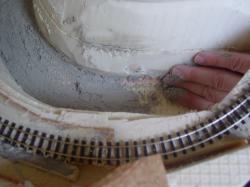
The lower track first bridge is positioned and the two ends of the river are removed. |
A closer look shows the necessary adjustments to the river shape. A small piece of styrofoam has been added. |
Minip_Im_114.jpg 344.72 KB |

Minip_Im_115.jpg 13 KB |
My daughter Camille finishes gluing the track platform. |
The river is now better looking. One will now have to shape it and get it real looking (a tough issue) before putting the bridges so the access would not be too difficult. This is the tricky model railroader choice: either getting the trains faster on track and having to spend more time on the landscaping with a destruction risk, or getting some of the big landscape points finished but moving faster on the tracks! |
Minip_Im_116.jpg 344.72 KB |
Minip_Im_117.jpg 13 KB |
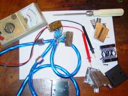
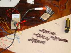
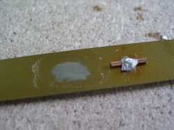
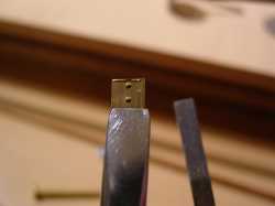
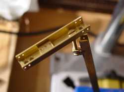
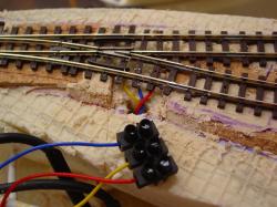
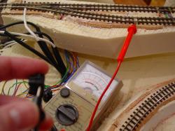
It is now high time to address the switches. A multimeter allows some connection verification and thanks to my daughter Camille, a very interesting one is found! The soldering iron and wire, and four sets of three wires will be enough. The wires are kept long to allow cutting them to the right length later on and keeping some length for repairing purposes The cutter is out! |
It is used to scratch the metal parts for a better soldering. |
Minip_Im_118.jpg 344.72 KB |
Minip_Im_119.jpg 13 KB |
Try out: getting the switch been piloted with a FAM. Soldering on a coated surface does not work well! |
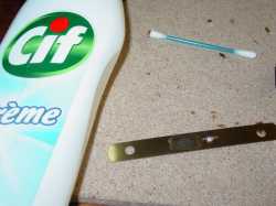
Removal of the coating using basic commercial products |
Minip_Im_120.jpg 344.72 KB |
Minip_Im_121.jpg 13 KB |
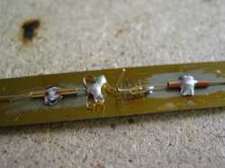
One can compare before and after |
The right soldering is much better, the technical strategy has unfortunately to be improved! |
Minip_Im_122.jpg 344.72 KB |
Minip_Im_123.jpg 13 KB |
However, it works. I should be able to get something appropriate by trial and errors! |
Within a very short time the result is available. Robust, not expansive, easy to build, it has only good features! |
Minip_Im_124.jpg 344.72 KB |
Minip_Im_125.jpg 13 KB |
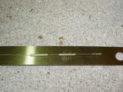
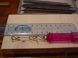
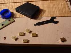
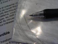
I just bought some springs. I need to test them priori mounting them when cut to the right size. One should expect getting a final spring for 0.30 Euros/0.20 Pounds/0.36 USD. This one comes from a Pro-rail FAM test kit. |
A simple marking allows to position the cutting lines and the holes boring locations. This does not need to be extremely precise, adjusting will be done when associating the devices with the switches. |
Minip_Im_126.jpg 344.72 KB |
Minip_Im_127.jpg 13 KB |
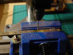
Boring can occur. Please note that although aligning all the points at first some variations occurred. This is due to the pressing on the level that moved the drilling tools from its boring location. This is not a major problem for the final use. |
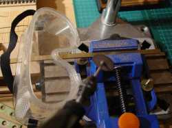
To cut the metal, a disc is perfect. One should wear protection glasses. As expected, cutting directly with only my hand as a guide got a disc to break. Only one millimeter of it was left! The glasses also allow to protect yourself from the tiny metal particles send everywhere when cutting with a disc. |
Minip_Im_128.jpg 344.72 KB |
Minip_Im_129.jpg 13 KB |
One should remove the left-over to ease the slipping parts movements. Good pliers and a small needle are perfect for this job. |
I need four pieces but did six. One was missed. One extra is left. |
Minip_Im_130.jpg 344.72 KB |
Minip_Im_131.jpg 13 KB |
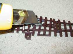
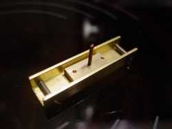
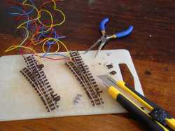
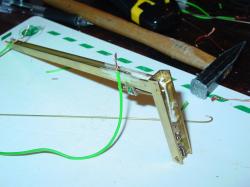
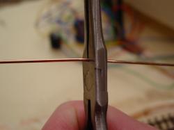
I only have fifteen minutes available to work on the module. I will prepare the switches. With a pliers I remove the rails ends and replace them with plastic ones. I got the last for 3.20 Euros/2.4 Pounds/3.90 USD for 24 Roco pieces. The cutter separates these small pieces which are coming per six at a time and allows to remove the switch motor setting -- along the switches -- that comes from the maker but is too big and not nice! |
Here we are! I finally had one hour and a half to address the switch mechanism. My idea about it has changed to cope for a simple solution still allowing a fine tuning of the system. Finally I found out that tuning the structure was simpler than adjusting the cable. I also chose a simple one screw solution rather than an insecure complex solution. See however the two wrong holes on the left I made them at first and found out they were too close one to the other. I took the tuning element and another piece of metal to find were to drill. It does not have to be precise. |
Minip_Im_132.jpg 344.72 KB |
Minip_Im_133.jpg 13 KB |
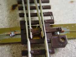
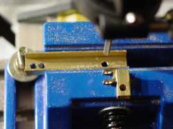
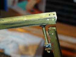
After soldering the tuning element, I can mount the structure. Some holes are made across the metal to allow positioning axles and thereafter the springs. |
The very simple mechanism from a closer look. The screw can be accessed from the top. We will come back on this later on! |
Minip_Im_134.jpg 344.72 KB |
Minip_Im_135.jpg |
The system is being tested, works well but is not perfect. We may try to find an easy way to make a simpler one when necessary! |
Minip_Im_136.jpg |
Minip_Im_137.jpg |
Remember our bridges story (pictures 47, and 100 to 114?). During a trip in Stuttgart I found a wonderful trains shop.. and metal bridges, which not only are not expensive but on top very fine! Here is one well its box! (one has to keep you reading on no?) |
Grr! I know your feeling! And to get pardoned, a little bit, I would like to show you part of the track Unfortunately, I forgot to take pictures of the lower track! On the other hand, you can see old glue being used for the bottom of the river! |
Minip_Im_138.jpg |
Minip_Im_139.jpg |
The radius of the track has been slightly increased. The track glued with Styrofoam glue was maintained by pins. |
The upper part of the lower track is electrically separated from the switch. The cables are set nearby. So this part can be handled separately. One can also see that a hole has been made underneath the switch to allow for a mechanism to be set in place later on. |
Minip_Im_140.jpg |
Minip_Im_141.jpg |
The upper track benefit from my brain being aware of taking pictures! It is cut and one immediately notice that the track shape will not fit with the bridge Either the bridge is kept straight and the track shape is changed, or a curved bridge has to be used instead. The first solution fits better my needs. |
The cutter blade is fully opened and cut underneath the ramp which is then cut into pieces. The are then recombined to fit a new shape. An adjustment of the pieces is made. The work turned out to be easier than expected. |
Minip_Im_142.jpg |
Minip_Im_143.jpg |
The ramp is glued in this new configuration. The good initial looking is not available anymore but on the other hand trains will have a more tortuous behaviour which is not bad for narrow gauge railways! |
The slope is not perfect and it barely glued. No problem, the track will compensate for that and experience shows that even a small amount of glue is enough. Full gluing can be done later. |
Minip_Im_144.jpg |
Minip_Im_145.jpg |
Styrofoam glue comes as a layer using your finger. This special glue (like peanut butter consistence) is easily washed out your skin (under water with soap). The glue thickness is set as small as possible -- it should not dry out too fast! |
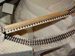
A piece of wood, of the same length as the bridge, is inserted between the rails (here we have 9mm gauge, the wood being a 8 mm squared section one) so the track stays straight! A piece of chocolate box is glued under the track. It will maintain it straight. (No need to press too much, there's no vertical constraint) |
Minip_Im_146.jpg |
Minip_Im_147.jpg |
While glue dries out, time is used to fill some left over holes. |
Electrical cable just look like mess! But the most important is that so far, each track cable has found its piped counterpart! It is better to separate the electrical part of the track prior to gluing them than later on. |
Minip_Im_148.jpg |
Minip_Im_149.jpg |
The bridge is brought in place. The piles are a little bit too modern to my eyes. Unfortunately it is too late to review the entire landscape conception! |
Piles needs to be adjusted to allow the train circulation on the lower track. Fortunately, this is not to be seen from the observer side! (It has nothing to do with real world!) A wide space is kept between the two tracks as wished in first place. This will leave a good observation capability for the eye. |
Minip_Im_150.jpg |
Minip_Im_151.jpg |
When the piles are set in a proper position, the less stable one is maintained by a piece of wood. Funny enough this is the same as the one used before! |
What about the lower track second bridge? At first I wanted to put a metallic one but finally a Styrofoam could make it! It just has to be smaller than the first one to give the illusion of distance as described in "Bon baiser de Ferbach". |
Minip_Im_152.jpg |
Minip_Im_153.jpg |
A second try is conclusive and the bridge can be glued in place! |
As I need to turn around the module, I just move it to another table. I take advantage of doing so to do a little bit of cleaning! This allows a picture of the current situation to be taken! |
Minip_Im_154.jpg |
Minip_Im_155.jpg |
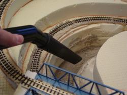
And from a different angle Oups! It is really high time for cleaning! |
The vacuum cleaner sucks all dirt, whether in the river or between the rails! |
Minip_Im_156.jpg |
Minip_Im_157.jpg |
Do you remember? The upper track was redone in one piece. Although this was useful for preparation purposes, this would not be convenient to have a station in a ramp Simply because one would not be able to store a coach there! This will be re-addressed! |
Two slices are removed from the Styrofoam. Unfortunately the cutter went a little bit far and I am afraid that this will not be resistant enough |
Minip_Im_158.jpg |
Minip_Im_159.jpg |
I am right! Five minutes after putting the ramp in place, its shape gets rather unusable! |
My baby Francois would like to "help" me I found out that it was more convenient to leave him playing with some Styrofoam nearby! |
Minip_Im_160.jpg |

Minip_Im_161.jpg |
On the other hand, my daughter Camille can really help! |
By setting in place the upper station. The Styrofoam is repaired. |
Minip_Im_162.jpg |
Minip_Im_163.jpg |
The ramp is glued step by step to allow later cutting for the bridges. |
Let's try another metallic bridge This is an N gauge one, almost too tight for the steam engine but still OK. (again the vision of the observer has to be tricked) |
Minip_Im_164.jpg |
Minip_Im_165.jpg |
The Styrofoam at the location of the bridge to come is removed. Although a bridge which would fit this location has not been found yet, it is easier to prepare the slot for it now rather than having to cut the Styrofoam later on. In this hobby, it is often easier to build later on that remove some existing parts! |
The track can now move on upwards! However, the first part of it is already in place. One has to ensure a continuum of the radius. This is why soldering is needed at this point. |
Minip_Im_166.jpg |
Minip_Im_167.jpg |
Rather good one. No left over on the track except for the melting facilitator means that cleaning will be an easy task with a rotating polishing brush. |
Unfortunately, an angle appeared when bending the flexible track. If one does not have the tool or does not want to preformed the flexible track as per by Jacques le Plat's council, the only possibility is to insert a curved piece of track. At the bottom is everything fine, upwards, the angle will disappear after positioning properly the flexible track. |
Minip_Im_168.jpg |
Minip_Im_169.jpg |
The track is glued as done before. The difference is now that the position of the track has to be kept precisely at the same time as being removed to put the glue. Thanks to the pins this is possible to move the track up by two centimeters and insert the glue in between. |
An ear stick allows to clean the excess of glue. As long as the glue does not affect the technical requirements for the model trains, this is of no relevance if it shows up. This part of the track will not be visible afterwards. |
Minip_Im_170.jpg |
Minip_Im_171.jpg |
A piece of track comes where the bridge will be. Unfortunately its direction does not fit the following part of the upper track. Bending the track by hand proves to be ok. |
A new comer, which we will see later on, forces me to increase the size of the upper station. This last is made with prefabricated segments without any problems. One just needs to remove some of the cork for the cables and make sure that the tracks are parallel. |
Minip_Im_172.jpg |
Minip_Im_173.jpg |
Saturday., January 12th First shock of the day! We offered ourselves a long sleep until nine o'clock in the morning enough for Francois to have a closer look at the work! So close that the bridge did not resist. I could put it back but with a painting scratch and one soldering point less. |
Some days are simply like that. You should avoid staying in your bed and at the same time waking up! Having some free time, I decided to cut the upper track before the switch. I forgot to press the track at the same time. The track vibrates, the disc breaks and the rail moves away. Its new shape does not allow for direct recovery. |
Minip_Im_174.jpg |
Minip_Im_175.jpg |
Recovery is a matter of time. A new piece of track being cut and bend, comes into place. The switch is brought at the same time. The glue is already there, One of the electrical wire leaves the center part of the switch! I am soldering it back. This is rather good. It would have been a disaster if broken in its final position with very limited access. |
A simple task is chosen: putting 76 centimeters of track on the upper part. The track adjustment will be done in the curve. the track is maintained in position with two copper plates and a small anvil. |
Minip_Im_176.jpg |
Minip_Im_177.jpg |
The newcomer is here along with some more to be used ones! |
A blank test is necessary to fix several issues. First, to align the tracks, and, at the same time, to reduce the number of cuts, the straight track is made of two straight track pieces. The curved one is adjusted with two curved pieces -- bought for this purpose -- so only one cut on a straight piece is required. The cables are soldered approximately at the same level on the two tracks. This is to avoid cutting the cork in several locations. The cork is also removed for the switch wires. |
Minip_Im_178.jpg |
Minip_Im_179.jpg |
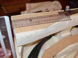
The tracks are glued using the eye to align them. Then a fine positioning using a straight piece of metal (a long ruler would make it) |
A picture is made and shown on a computer screen to check the alignment. Everything seems to be OK. |
Minip_Im_180.jpg |
Minip_Im_181.jpg |
Only one piece of curve, less than fifty centimeters, is still missing. I should already worry for the electrical logic to run the tracks! |
The last piece of track is bended, bended again, it resists! However it ends up by being cut and glued along with a know well known procedure. Where the track cannot be lifted, the glue is pushed underneath using a small piece of strong paper. |
Minip_Im_182.jpg |
Minip_Im_183.jpg |
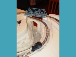
Looking from the top shows the tracks as once dreamt, or almost, about 180 pictures ago, as well as one and a half year ago! |
A cut is made nearby the track to pass discreetly the cables. Underneath, they will be retrieved and connected. |
Minip_Im_184.jpg |
Minip_Im_185.jpg |
The same is done for the intermediate train station. A saw (children game) is used. It is rigid and long enough to penetrate the Styrofoam without bending. |
It fits perfectly the work need. Dust is then vacuum cleaned, as is now regularly the module as well. The first trains should come soon! |
Minip_Im_186.jpg |
Minip_Im_187.jpg |
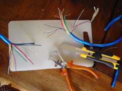
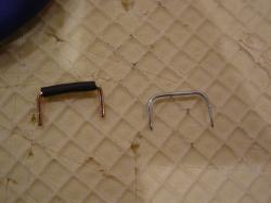
Cables are for the time being linked to electrical removable connectors. This will allow changes if needed during the test phase. |
A balloon metallic handle, pliers which is used to cut, folding several times on the same spot, as well as to fold, and within a few minutes |
Minip_Im_188.jpg |
Minip_Im_189.jpg |
For the other cables, some cut guides are realized and cables are simply maintained in those using Styrofoam left over from their cutting! |
Minip_Im_190.jpg |
Minip_Im_191.jpg |
Each piece of track is tested and everything seems to be OK. A marking directly on the Styrofoam allows to identify the tested regions. |
I take advantage of this to take a picture of the upper ramp. There's still plenty of work to be achieved! |
Minip_Im_192.jpg |
Minip_Im_193.jpg |
All track sectors are ok, all but the center of this switch! That's simply surprising since all switched have been tested several times before setting them in place Murphy is still alive! Some removal will have to be scheduled! |
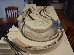
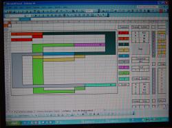
Except for the trains, I am also found of Excel (Lotus!) And I simulated the circulation of the trains using a combination of data sheet functions and macros. The track shape can be changed but the crossing logic has been hard coded (I did not need a dynamic one). Here my trains are moving taking care of each section occupation as well as scheduled movements. For example, a train in sector 9, upper station, which got the order to move down locks the upwards movement of a train in the intermediate station even though sector seven is free. |
Minip_Im_194.jpg |
Minip_Im_195.jpg |
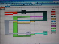
The wish to get the logic behind the train circulation gave the opportunity to draw the track scheme. This drawing is now used to report the connections, as soon as they are tested. This means there's no need to come back on the power line connections drawing afterwards. Every chance to win time later on is to be used! |
On these connectors, the position of each cable is made according to the section sequence number. This will make it easier for maintenance. This is also important since I may use these connectors for a while, at least until a very advanced stage of the module. |
Minip_Im_196.jpg |
Minip_Im_197.jpg |
The switch problem is still in my mind! To cut at best the Styrofoam I need to make sure this will not have any impact on the ramp. Two small Styrofoam blocks are added underneath the ramp. |
After cutting, I am playing with my new toy a dentist mirror (and its associated tartar remover) which I got for less than three euros (2 Pounds/4.5 USD) But what? The soldering is still OK and the wire as well |
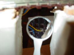
Minip_Im_198.jpg |
Minip_Im_199.jpg |
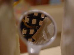
A closer look allows to identify two small spots which seem to are the actual connection to work or not. Either I need more soldering or to squeeze it I ask the group "ptitrain" for councils! |
Straps are prepared from a balloon handle and a thermo retractable isolating form. It turns out to be too big for both of them to fit simultaneously in the connectors. MIMO ! South east Asian toys straps makes good material for this purpose and, on top for free! |
Minip_Im_200.jpg |
Minip_Im_201.jpg |
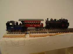
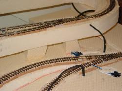
The first Roco train run on the track is made possible thanks to |
a huge sets of those but it does not matter! What is important is the joy to get the first train on the tracks! This actually allows for some minor corrections of the Styrofoam shapes nearby the track. |
Minip_Im_202.jpg |
Minip_Im_203.jpg |
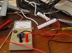
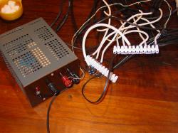
Tests are made under very strange conditions but with a power supply designed by "Ptitrain"! Although this power supply is protected against short circuit with a 20 W halogen bulb, I prefer to check the actual electrical separation of both tracks before connecting them. This turns out to be useful as an error occurred. (Isn't it better to find it now?) |